This was the final project my group came up with for ECE 3161: Introduction to Robotics at the University of Connecticut.
My involvement in this project was primarily the mechanical design since my groupmates didn’t have experience. In the future I would like to replace the cheap $5 servo motors with stepper motors for better performance. It was fun to pretend to be a mechanical engineer for a few weeks but next time I’ll just code the controller instead 😀
I found this design online that I am just itching to replicate for next time.
Objectives
Our goal was to design and manufacture a 3-DOF robot arm capable of drawing/painting simple shapes on a canvas. This would require us to
- Derive forward kinematics and DH parameters
- Derive and program inverse kinematics
- Convert simple paths to robot arm commands
My personal objectives with the mechanical design was to make it easy to construct, fast to prototype, and use cheap/readily available parts.
Features
-
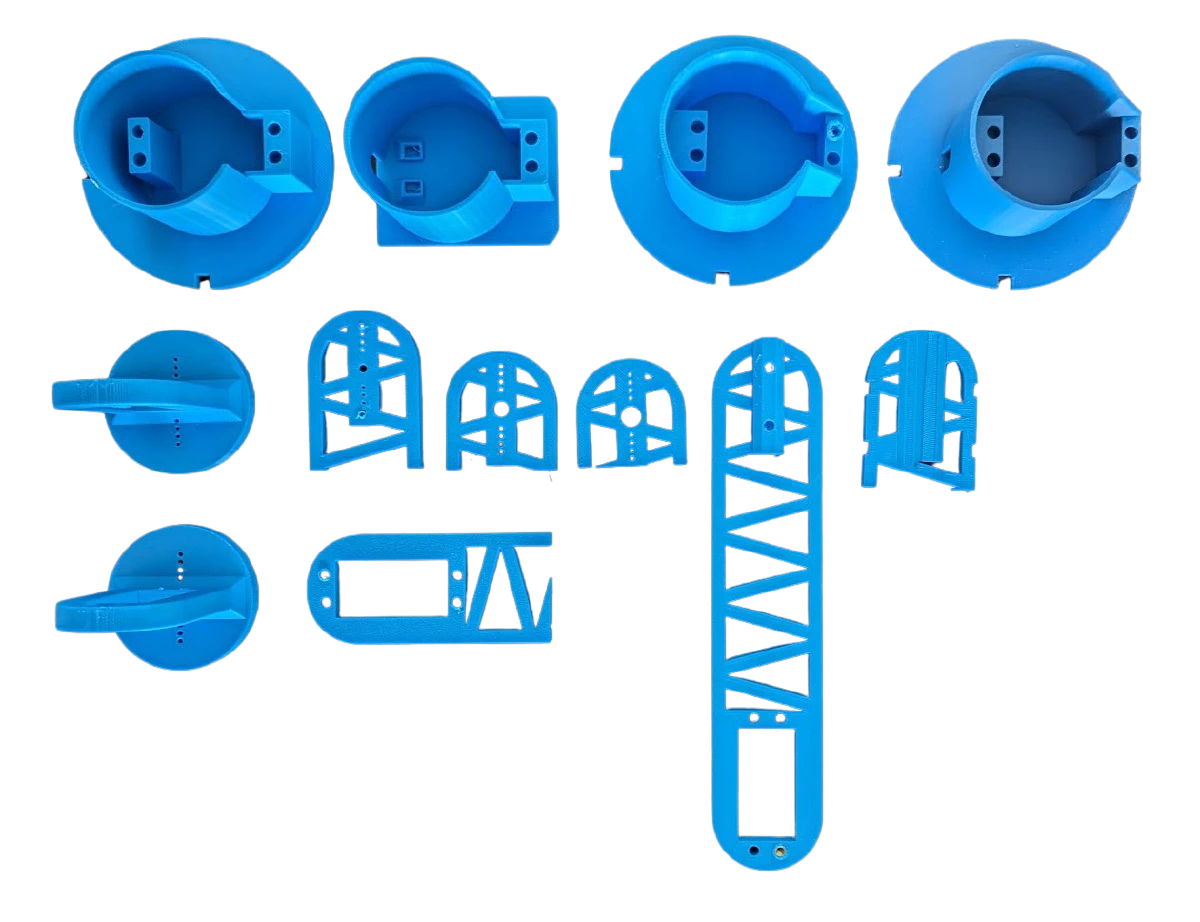
Easy to manufacture Most components are printable without support and screw hole features won’t wear away since threaded inserts are used.
-
Customizable: The robot assembly and 3D models have parameterized dimensions to account for printer tolerance or to scale the part sizes. Note change parameters at your own risk since some changes will require manual modifications, such as the “truss” structure for the links.
And thankfully the end effector fits most writing/drawing utensils.
Design process
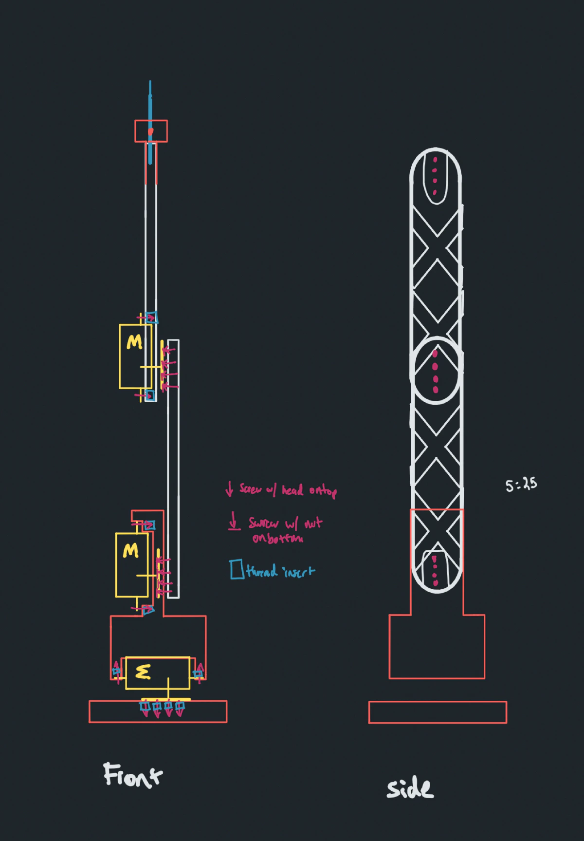
I started by creating sketches of the robot arm using the Concepts iOS app (I highly recommend it). It was difficult for me to visualize how to mount the links to the servo motors since there is practically only one method of mounting.
I decided to use OnShape as my 3D modeling software. As someone who has come from an Inventor/Fusion 360 background the switch was easy. I am a big fan of their source control feature not to mention that I can run it on my Linux laptop!
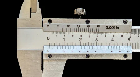
What really leveled up my functional 3D printed parts was compensating for the tolerance of the printer. If you want anything to fit together, guess and check will only get you so far. A dead simple option is to print this tolerance test. I would also suggest purchasing a caliper. A standard ruler can only do so much.
Also consider purchasing some threaded inserts for screw holes. It will save you from throwing out your parts after a few re-assemblies.
My love hate relationship with 3D printing reached a breaking point. I could not bring myself to tweak my Ender 3 for the 5,000th time in order to maybe have a part that works. I realized that I like to 3D print, not fix my 3D printer. My soul could only take so many failed prints before I lose interest in a project all together. So I plunked down the money for a Bambu P1S. And boy does it crank out flawless parts with minimal effort. Not to mention that printing times are a third of my ender. It certaintly helped me embrace the iterate fast, break things quickly mantra.
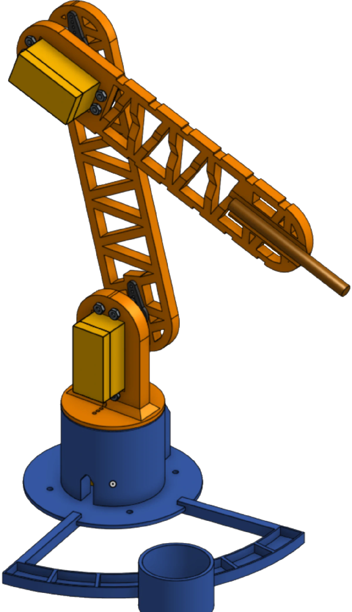
Here is the final product.
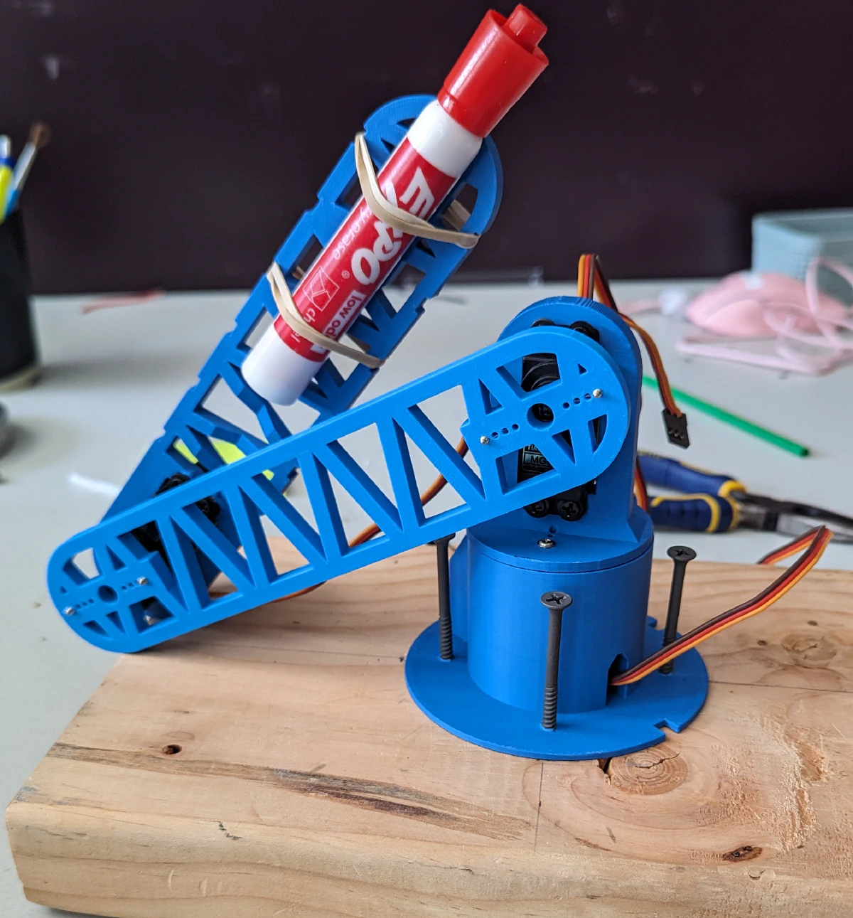
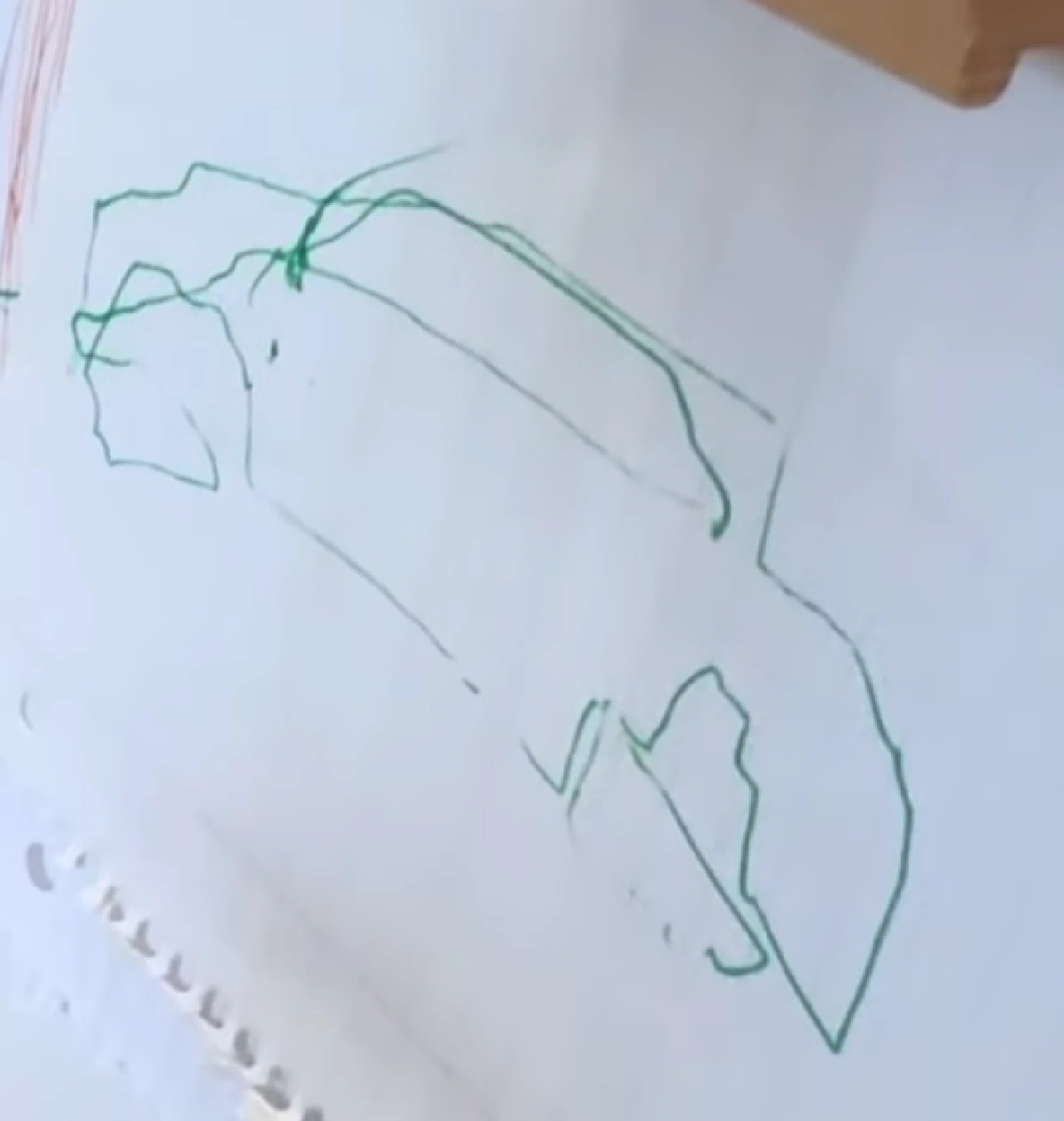
How does it work? Well… not the best. Rembrandt may have been a classical painter, but Rembrot is certainly an abstract painter.
Math
For someone who may not have covered how to mathematically model a robot, the rest of this section will look like absolute gibberish. But if you are just getting started with robotics I highly encourage you to try and use plain old trigonometry. That is all you really need. With that said, let’s continue on.
If you apply the Denavit–Hartenberg convention you get a table that looks something like this
| link # | $\theta_i$ | $d_i$ | $\alpha_i$ | $a_i$ |
|---|---|---|---|---|
| 1 | $\theta_1$ | $l_1$ | 90 | 0 |
| 2 | $\theta_2$ | 0 | $l_2$ | 0 |
| 3 | $\theta_3$ | 0 | $l_3$ | 0 |
Here is a fantastic visualization of what each of the parameters mean
Note to self. The row describes how to modify the frame of reference from the start of the link in order to get the frame of reference at the end of the link.
Let $A_i$ represent the total transformation from frame $F_{i-1}$ to $F_{i}$. To get the actual transformation for a single link using the DH convention we use
$$A_i = Rot_{z, \theta_i} Trans_{z, d_i} Trans_{x, a_i} Rot_{x, \alpha_i}$$
The total transformation is $T_i = A_1 A_2 A_3$. The order is reversed because the transformationed are with respect to the a relative frame. In other words, the links orientation depends on the ones before it.
Before taking this course I thought that inverse kinematics must have had some kind of incredibly elegant solution. But plain old trigonometry is really all you need. The final formulas are pretty messy, but at some point I will come back and include a full derivation. For my 3 degree of freedom design you have:
Let $D= \frac{x_c ^2 + y_c ^2 - l_2^2 -l_3^2}{-2 l_2 l_3}$. $$ \begin{aligned} \theta_1 &= arctan(x_c, y_c)\\ \theta_3 &= \frac{arctan(\pm \sqrt{1 - D^2})}{D} \\ \theta_2 &= arctan\left(\frac{z_c - l_1}{\sqrt{x_c^2 + y_c^2}}\right) - arctan\left(\frac{l_3 sin(\theta_3)}{l_2 + l_3 cos(\theta_3)}\right) \end{aligned} $$
Issues
So clearly there is a lot of room for improvement. I can’t speak about the quality of the code but our cheap hardware surely didn’t help. The base was more wobbly than I liked, but is easily fixable, which is why the drawing is so shaky. The precision of the servo motors are also a limiting factor.
For our purposes the robot arm did the job. But if the end effector had to be something more weighty this arm is a bad idea. The motors are the only thing holding the links together which definitely puts too much stress on the construction of the motor. Unfortunately I don’t think there are many other ways to mount a cheap servo motor. At least stepper motors have screws that logically make sense.
Rembrot
Inducted May 16, 2024
A 3 DOF robotic painter
Recent logs