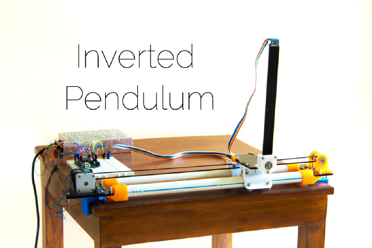
Inverted pendulum construction
It’s mostly ready to wire up!
June 14, 2023
This is a part of my self-stabilizing bicycle series, which you can learn more about here
This weeks progress
It is pretty difficult to work on projects on your own time. It’s a golden opportunity to find creatives ways to procrastinate. I found myself more than once screwing around with my Neovim configuration or my website’s CSS instead of programming what I needed.
That’s an issue I’ve been trying to deal with since starting college. I found that while I was in high school I was much more willing to settle for a piece of code that “just works”. Nowadays, I find it much more difficult to get myself to throw together a script to accomplish something quickly. I believe it’s a case of paralysis analysis. If I wasn’t so concerned with outcomes and doing things right the first time, I’m sure I would have made much more progress than I currently am at. As they say, perfection is the enemy of good enough. My procrastination behavior, paradoxically, stems from my aversion to wasting time.
The hilarious part is that I actually waste time by worrying about wasting time. My mindset isn’t in rapid prototyping mode. Instead I painstakingly engineering something and attempt to foresee all the possible kinks. It’s something I’m working toward escaping, but for now, it is quite present while working on this project.
Design methodology
Before you learn how to run, you need to learn how to walk. I am not a mechanical nor an electrical engineer, and quite frankly, I do not currently possess the hard skills to construct a self stabilizing bicycle. So I have to start by learning the basics.
Learning to control an inverted pendulum (IP) is a logical first step towards building a stabilized bicycle. In general, developing an IP control system is one of the best starting points to learn linear and non-linear control schemes. The r/ControlTheory Reddit is filled with videos of them. A bicycle can also be modeled as an IP assuming that the tires remain in contact with the ground at all times. A lot of other things can be modeled as inverted pendulums such as rockets.
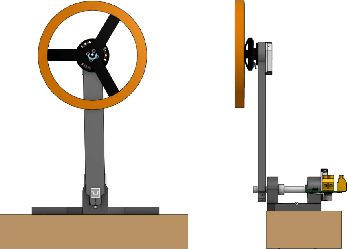
I specifically chose to use a r0px 29pxeaction wheel to stabilize an IP since many stabilized bicycle designs do so. I also like this type of pendulum from ease of construction standpoint. It is mechanically simpler and more self-contained compared to the standard “cart and rod” pendulum.
There are a lot of other subsystems that need to get worked out to build a stabilizing bicycle, such as steering, propulsion, and power (more here). I’ll eventually worry about those once I get there. I’ve learned from experience that worrying about every possible factor will make your head spin right off.
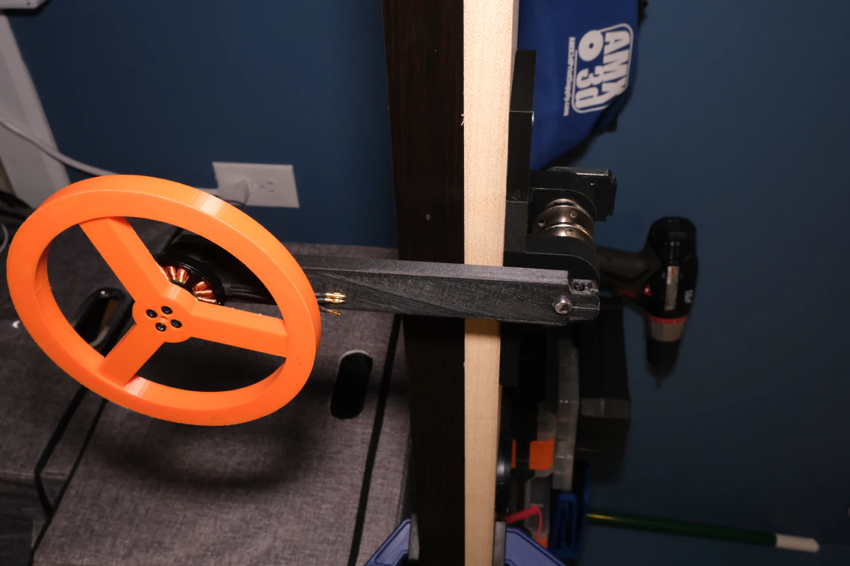
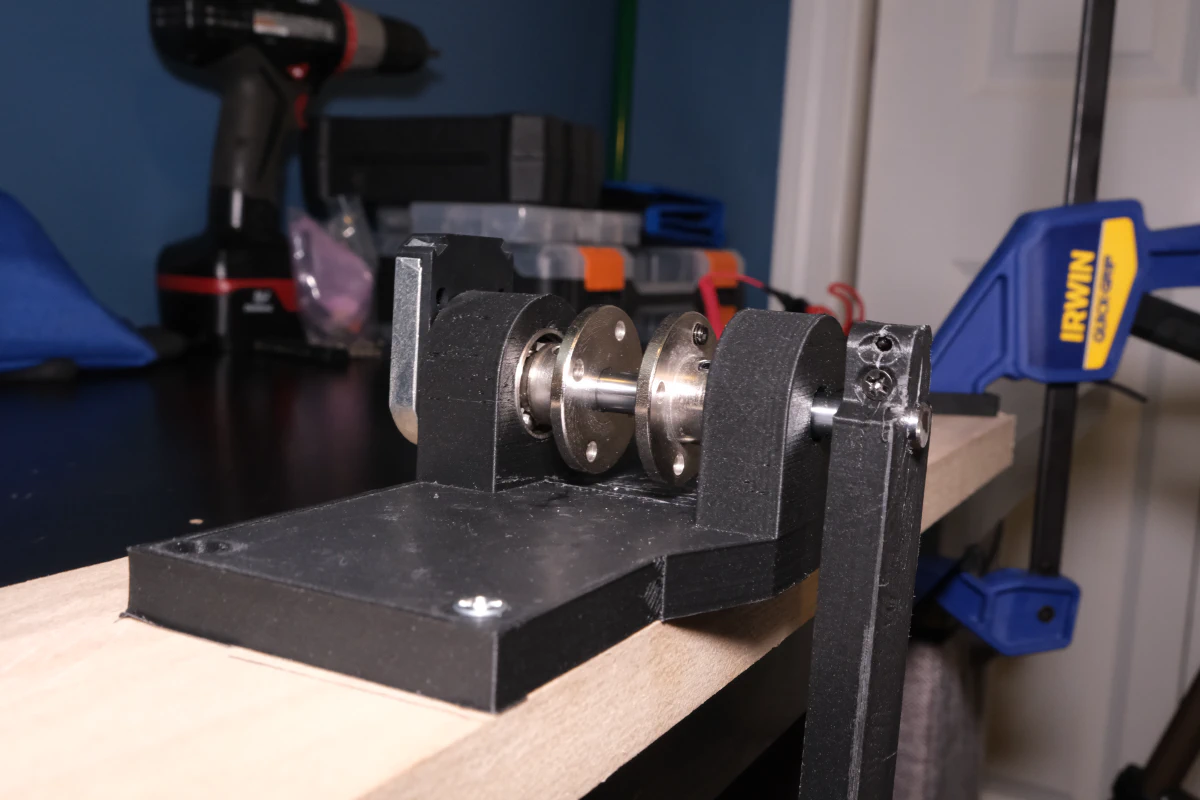
My reaction wheel IP
The design of an inverted pendulum is relatively straightforward. You have a free-spinning arm that is attached to a controllable wheel at the end of it. By accelerating the wheel, this induces an angular momentum on the system and causes the arm to swing upwards.
Since we hope to control this system, we need some kind of feedback to inform us of the state of the system at all times. That way we can course-correct the system. I am using an ODrive for motor control, AMT-102 encoders for feedback, and Antigravity KV300 brushless DC motors. These are the components I happen to have on hand from a previous project. Other than that, you don’t need much. All you need is access to a 3D printer, some screws, an axle, and skater bearings. A full parts list and CAD model is provided at the end of the article.
I’ve designed a decent number of things in CAD, but what made a massive difference while I was designing was having a ruler in front of me. I wasn’t working under many constraints, other than the size of my print bed and the screw locations of the encoders and motors. I found it difficult to decide what arbitrary lengths to use, so I used my ruler to get a feel for what was right.
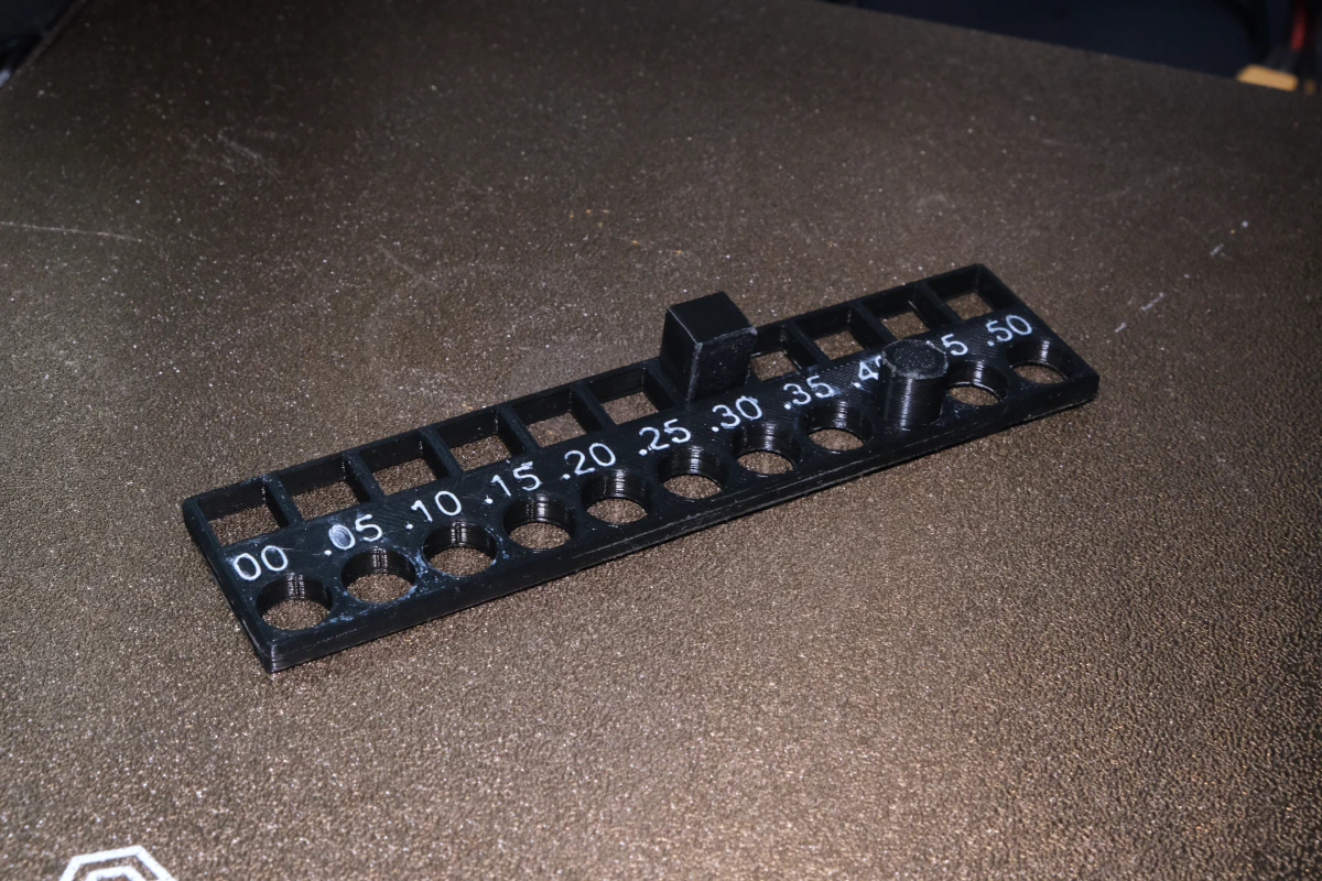
Another significant upgrade to my workflow was measuring my 3D printer’s tolerance for different kinds of fits. This informed the design of a lot of the 3D printed components, more than I thought it would. In the past I had never considered tolerances beyond trial and error adjusting my CAD designs. I had no desire to waste time like that again, so I found this part on Thingiverse test to measure your tolerance. I also heard that you can adjust your printer’s steps/mm to get more accurate prints, which I intent to follow up on at some point.
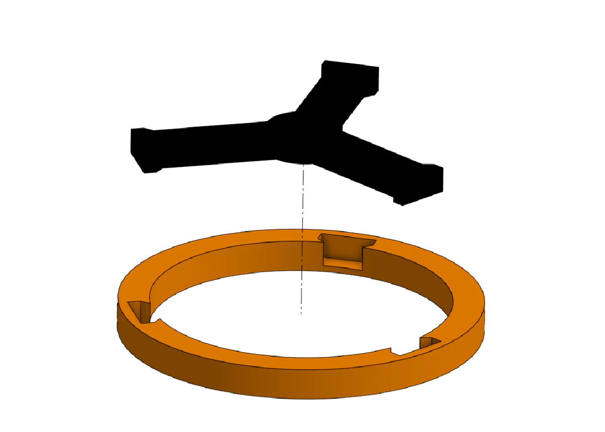
I used a snap-fit to combine the flywheel and its support together. This was so I could print the ring at 100% infill and the support at 20% infill to squeeze out a little more moment of inertia for the flywheel.
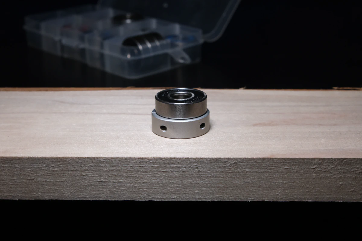
While I was researching on how to mount parts to an axle, to my surprise, I saw that for a lot of applications interference fits (held in place via friction) are used. I figured there was a better way than that, but I suppose not for relatively small applications.
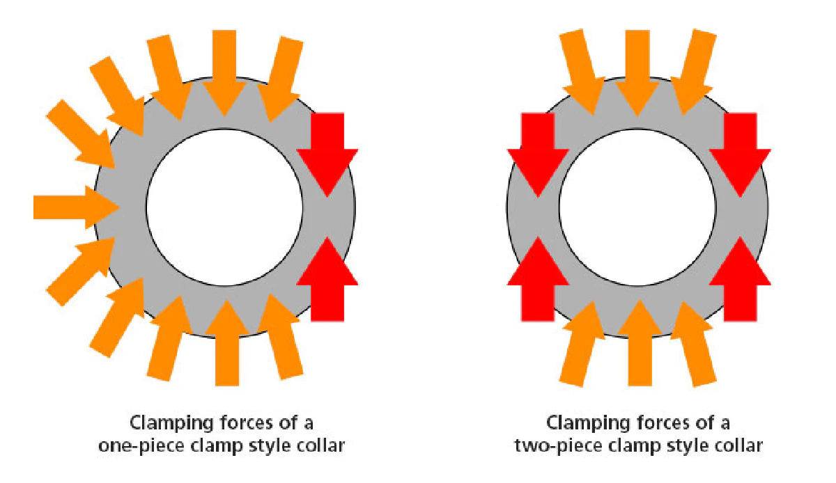
I decided to use a two-piece shaft collar to hold the axle in place since the clamping forces are more evenly distributed across the collar and they don’t scratch up the rod with a set screw. If you want to learn more about various types of shaft collars, I would recommend this article and McMaster-Carr to find a wide selection of them. I also purchased some flange couplers since those are handy to have in general.
Printing time!
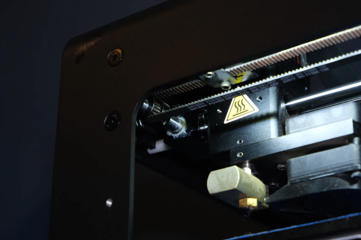
What’s better than a 3D printer? Two 3D printers!
I brought home my old 3D printer that was gathering dust in the basement. There’s not really enough space to have one printer, let alone two, in a dorm room. This was the first time I had lubricated my 3D printer and it was… messy. I’m definitely not doing that indoors again.
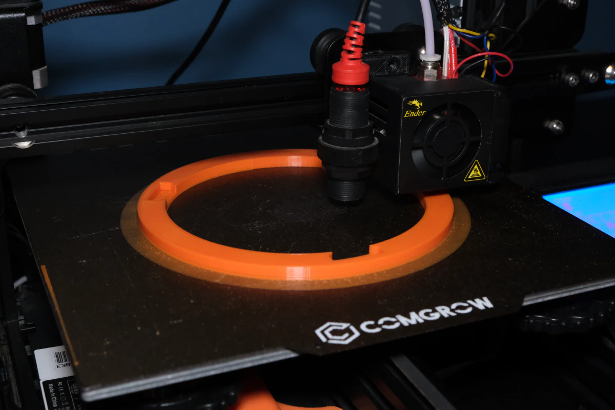
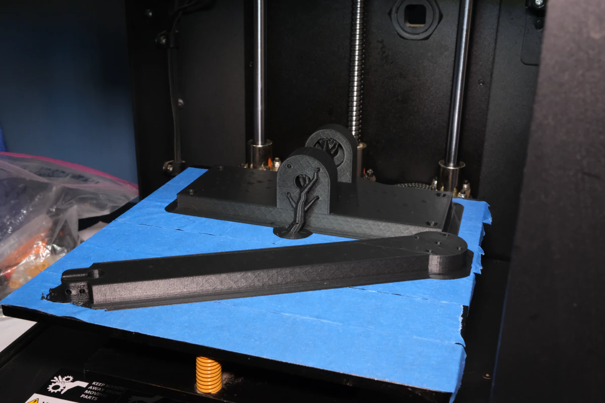
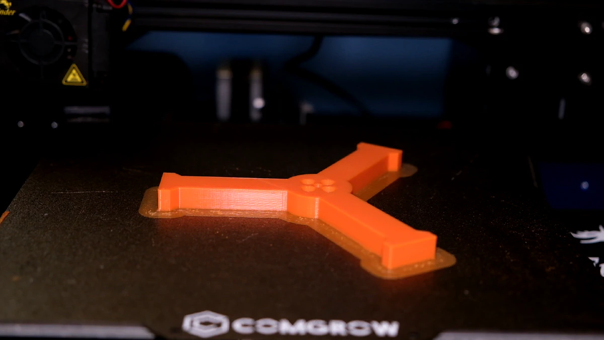
But now I am officially manufacturing at full capacity with an Ender 3 and a Wanhao Duplicator 6. I printed all the components and they came out pretty great! The tolerance of the flywheel components worked exactly as predicted (+0.25 mm extra margin for a snap fit).
Assembly
It was a visceral feeling to have constructed something I only imagined in my head a few weeks ago. It was incredibly satisfying to have it work as I mostly intended. I get the same feeling after coding too, but this was definitely higher potency.
There were a few hiccups while building, but nothing urgent fortunately. If these issues end up being a bigger problem than I expect, I’ll make Mark II with corrections.
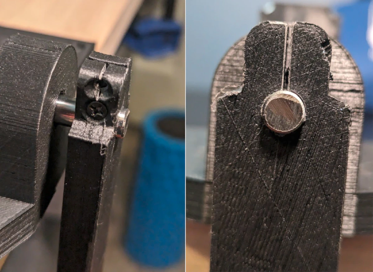
Issue 1: Preventing lateral axle movement
I thought it was enough to slap on a shaft collar and call this problem solved. For whatever reason I anticipated that I would need only one shaft collar along the axle. With such a setup there was too much play when the pendulum swung. It was an easy fix. I added another shaft collar.
You might notice that the parts along the axle are not shaft collars but flanges. This was my hack to temporarily address several friction issues as I wait for new parts. One cause of unnecessary friction was from the shaft collars sitting flush against the bearing and the base.
I tried using flanges since they have a smaller diameter. But I was, for some reason, still having friction issues. It turns out that the dust cover of the skate bearing was coming into contact with the flange if the flanges were applying too much pressure. No cover, no problem!
These fixes are doing the trick for now, but to properly address these issues I need a spacer with the same dimensions as the inner race/ring of the bearing to stack on (thanks stuffmadehere!). I believe this will be suitable.

Issue 2: Motor axle holes are too small
I had to increase the diameter of the holes to fit the motor axle using a drill. It’s good enough for my purpose, but if I’m going back and fixing the design I will definitely update this.
Issue 3: Less than ideal arm mounting
The pendulum arm is held on using only friction. Since it is plastic on metal contact, the arm does not have a very good grip. It isn’t bad enough to warrant fixing immediately unless there are issues later on. I tried tightening the screws for better grip. 1 screw tightened did help. 2 screws caused it to snap. It is still working for now. I should consider mounting a flange instead. Or alternatively, I can make the adjustable hole more compliant. In the same way I have a space between the two sides of the hole, I can extend the space further downwards. This fix is inspired from how the two piece shaft collar works.
Parts List
CAD Files here: Onshape Inverted Pendulum
Note: You can adjust the Flywheel document to your printer tolerance using the variable studio.
| Quantity | Part | Where to acquire |
|---|---|---|
| 1 | Flywheel | CAD/3D print |
| 1 | Flywheel support | CAD/3D print |
| 1 | Pendulum arm | CAD/3D print |
| 1 | Pendulum base | CAD/3D print |
| 1 | 8mm x (approximately 100mm) motor shaft | Amazon |
| 2 | 8mm Skater bearings (608RS) | Amazon |
| 1 | Assorted M3x0.5 screws - 6mm (x4), 12mm (x6), 16mm (x4) | Amazon |
| 1 | 8mm inner diameter shaft collar | Amazon |
| 1 | Antigravity KV300 Motor (or any other BLDC motor) | TMotor Store |
| 2 | AMT102-V Rotary Encoder (these things are awesome!) | Digikey |
| 2 | Bar clamps (anything will do) | Any hardware store |
| 1 | 1in x 4in x 2ft Wood plank | Any hardware store |
| 4 | Wood Screws No. 8 x 1-1/2" | Any hardware store |